I usually record rides with my Google Nexus 4 phone, which seems to do a very bad job of recording the elevation. With an accurate DEM, and points snapped to an accurate road network, it becomes possible to recalculate the elevation of each track node and then determine the slope of each segment.
Assuming the track and the DEM are loaded into a PostGIS database, this is easily done with a couple of SQL queries.
The first query updates the elevation of the track with new values read from the DEM using the snapped points:
update points
set geom_snap=st_geomfromtext(
    'POINTZ(' || st_x(geom_snap) || ' ' || st_y(geom_snap) || ' ' ||
        st_value(rast, geom_snap) || ')', 32610)
from dem
where ride_id=$1 and st_contains(st_convexhull(rast), geom_snap);
This query assembles a new 3D point from the horizontal coordinates of the original snapped point and a new z-value read from the raster. Using the spatial (GiST) index on the raster table, the query takes 2770ms over 2243 points on my development machine. Not super fast, but acceptable.
The next step is to calculate slope. The first point in the track has a slope of zero, and every subsequent point’s slope is calculated between itself, and the previous one. This can also be accomplished with an SQL query:
with t as (
    select
        row_number() over(partition by ride_id order by id) as seq,
        id, geom_snap
    from points
    where ride_id=11
    order by id
)
select (st_z(p1)-st_z(p2))/st_distance(p1, p2)
from (
    select a.geom_snap as p1, b.geom_snap as p2
    from t a, t b
    where a.seq=b.seq+1
) as u;
This query uses the row_number window function to create a sequential ID for each point in the selection from the points table. All nodes from all GPX tracks are stored in the same table, so it is possible to have interleaved row IDs from different rides. If we wanted to extract sequential points from a ride, we could not depend on these IDs because they might not be consecutive.
The subquery (t) is used to extract pairs of consecutive points by performing a Cartesian product on two instances of the subquery, filtered by points that have consecutive sequence numbers.
So far so good, but there’s a problem: This query doesn’t protect against coincident points, which have a distance of zero, resulting in a division-by-zero error. That’s easy enough to correct, but why would it happen in the first place? Coincident points are pretty unlikely in the real world… The answer is that the snapping procedure may have snapped some points to the same location — in particular, this can happen when two points are snapped to the endpoint of a segment that is nearest to both. That’s the hypothesis, anyway.
with t as (
    select
        row_number() over(partition by ride_id order by id) as seq,
        id, geom_snap
    from points
    where ride_id=11
    order by id
)
select id1, id2
from (
    select a.id as id1, b.id as id2, a.geom_snap as p1, b.geom_snap as p2
    from t a, t b
    where a.seq=b.seq+1
) as u
where st_distance(p1, p2)=0;
Here, I’ve modified the slope query to find IDs of coincident points, and there are many!
 id1  |  id2
-------+-------
 11711 | 11710
 11712 | 11711
 11713 | 11712
 11714 | 11713
 11986 | 11985
 12240 | 12239
 12241 | 12240
 12305 | 12304
 12489 | 12488
 12490 | 12489
 12491 | 12490
 (etc...)
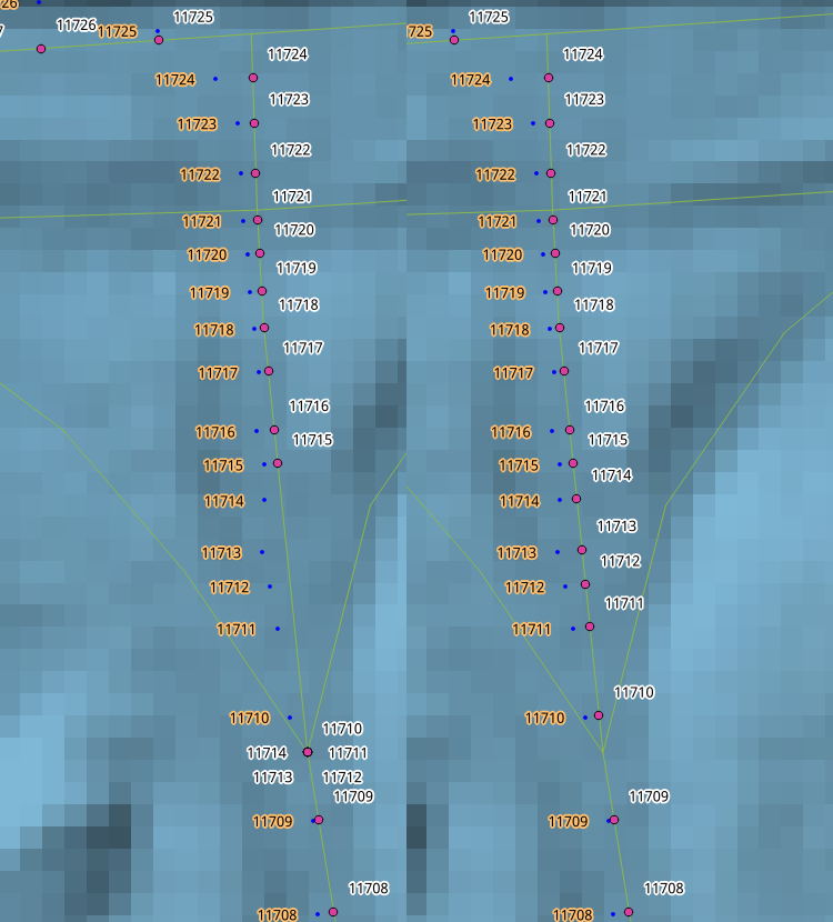
Snapping fix
It’s easy to see from this image that several of the original (blue) points have been snapped to the previous segment, and are grouped in the same place. Fortunately the fix is easy. In the snapping algorithm (implemented as a plpython function), the last segment is not included in the set of geometry IDs returned by the Dijkstra function, but it is known, because the second anchor point is associated with it. Adding this segments to the proximity search solves the problem.
But there are other problems:
- When the route rounds a corner, the GPS points tend to bunch up because they snap to the nearest edge, which is aligned so that it’s first vertex is closest to the points. I would need to space the points out somehow. I’ve elected to do this by spacing them out proportionally along the shortest route between two confident points.
- It turns out not to be possible to avoid snapping some points to ways that are parallel to the actual way that was used. This problem is not solvable — the machine has no way of knowing whether I was riding on the trail, or on the road that runs parallel to it. The only way to fix this is to manually edit the track, something I’d like to avoid. I’ve solved this problem, tentatively, by eliminating some classes of road segment from the confident point-finding algorithm. That is, only points that are unambiguously associated with a road or a bike path are allowed.
- Etc.
At some point, though, I just have to accept that the system cannot be perfected and move forward with the project. So here are two final interesting issues.
One of the artifacts of LiDAR classification is the removal of bridges. The abutments of the Johnson Street Bridge (left) are tall and steep, and the slope-finding algorithm thinks that I have ridden down to the surface of the water, a slope of -67%. Steep! Not much I can do about that.
The other issue is that the maintainers of Open Street Map are a little too ambitious. The bridge is currently under construction, and the approaches have changed. The new route and the old route are represented in the line work, but the temporary route isn’t. The algorithm follows the GPS track as far as it can, then backs up and takes a more plausible route — the old one — and snaps correctly to it. The under-construction route is labelled, “construction,” but for now it does not accurately represent the path of the road.
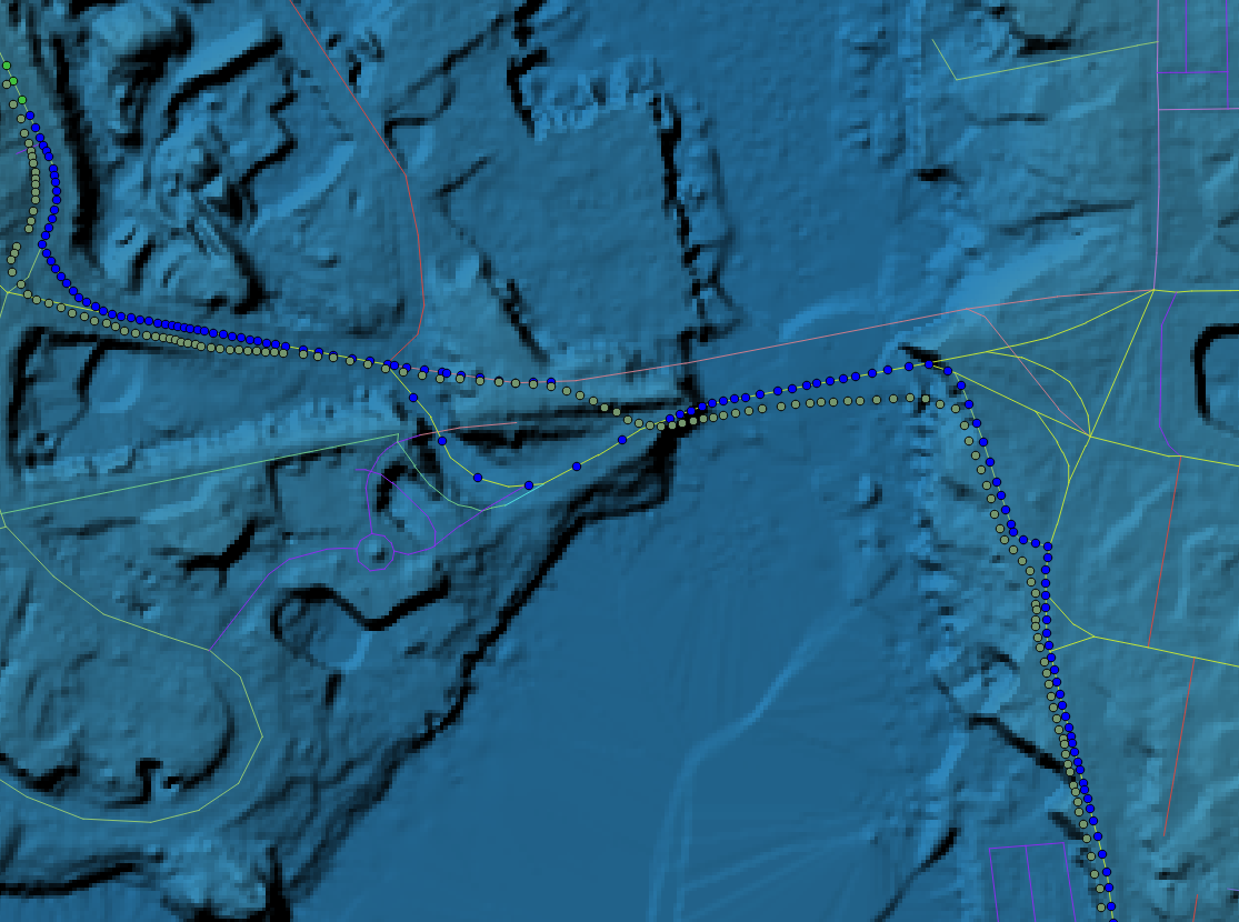
Johnson Street Bridge route snapping
Now, each GPS position has an accurate elevation and slope — sort of — but as I mentioned earlier, there’s no real basis for positioning the GPS points where they are along the road, even if I know I was on the road. The reasoning behind this strategy is that the vertical error introduced by using points that are a few meters out of place along a road are much smaller than errors introduced by not having points on the road in the first place.
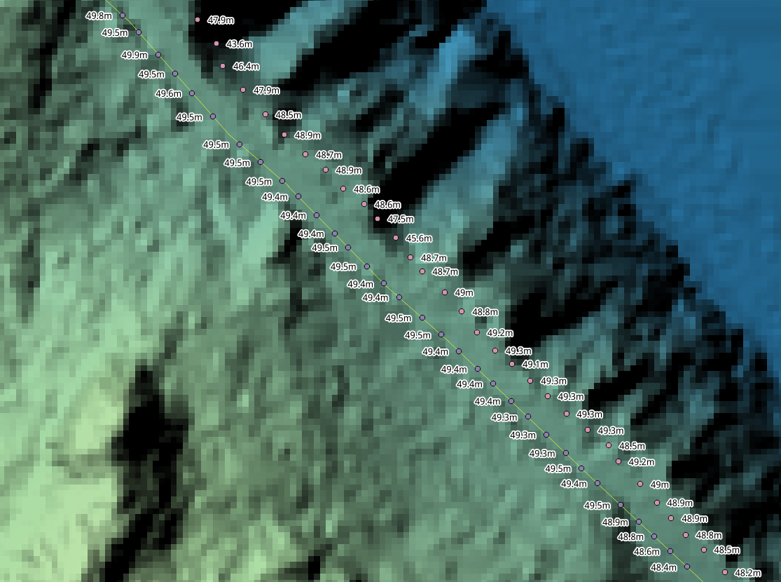
Elevation difference of snapped points
The last image on the right demonstrates the advantage. One of the original GPS points is in a ravine, nearly six meters below the surface of the road! The snapped points show a much more consistent, realistic gradient.
This looks really good. Nice to see the final image! Yay snapping!